Schlenk Lines and
Vacuum Lines
Introduction
Schlenk lines and vacuum lines provide a convenient means of manipulating
air and water-sensitive materials without the use of an inert
atmosphere glove box. There is no strict definition that divides the
term "Schlenk line" from "vacuum line", "chemical transfer line" or "vacuum
transfer line", but in some general distinctions can be drawn:
-
Vacuum lines usually have a better vacuum (10-4 to 10-7
torr) than Schlenk lines (10-2 to 10-4torr), because
vacuum lines typically have a diffusion pump. A way of delineating these
would be to use the terms "Schlenk line" and "High vacuum line".
-
Vacuum lines usually connect to the experimental apparatus with joints,
which provide a better seal and vacuum than the simple rubber pressure
tubing connections used on Schlenk lines.
-
Manipulations involving the measurement or condensation of gases are usually
performed on a high vacuum line. Operations involving cannulas
and counterflow
techniques are usually performed on Schlenk lines. The truth of this
statement varies from laboratory to laboratory!
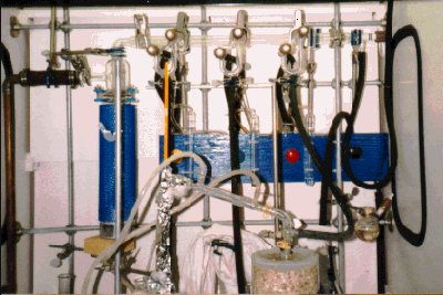
A Schlenk Line
A Schlenk or high vacuum line consists of a manifold that has several
stopcocks,
valves or openings in addition to a connection to a vacuum source (typically
a mechanical and/or diffusion pump). Having several ports on the line is
convenient because several different flasks or reaction vessels may be
used simultaneously. For example, gases can be vacuum transferred from
one flask to another or several reactions may be run at the same time.
These lines may be of a dual or single manifold design. In a single
manifold design, the manifold's main purpose is for vacuum. Here is an
example of a single manifold design which uses all-Teflon(tm) valves and
O-ring joints to ensure a good vacuum seal. Each port has its own independent
bubbler,
so up to three reactions can be stirring under nitrogen at one time.

A dual manifold design provides one manifold for vacuum and another
for nitrogen or a reactant gas. A connection between the two manifolds
permits the nitrogen manifold to be easily evacuated.
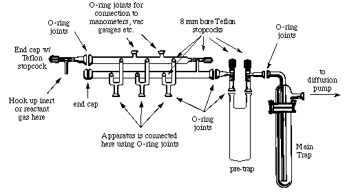
A Vacuum Line
Shown below is a diagram of a dual manifold high
vacuum line. Note that the lower manifold is for vacuum and the upper one
is for nitrogen.

Two features worth noting in this drawing are:
-
Main Trap. When the line is running, this trap is immersed in a
liquid nitrogen dewar. This stops volatile or corrosive vapors that have
escaped the pre-trap and prevents them from entering the pump. New pumps
can cost one to two thousand dollars, so protecting the pump is its ONLY
role. NEVER PULL SOLVENTS INTO THE MAIN TRAP!
Pre-Trap. This is an additional liquid nitrogen trap to condense
vapors or gases from the vacuum line. It is also used to collect solvents
that are removed from reaction flasks. If you are removing a lot of solvent
from a reaction the nitrogen level will drop quickly, so be sure to keep
an eye on it.
Please return to the referring
document and note the hypertext link that led you here.

