X-ray crystallography is an experimental technique that exploits the fact
that X-rays are
diffracted by crystals. It is not an imaging technique.
X-rays have the proper wavelength (in the Ångström range, ~10-8 cm) to be
scattered by the electron cloud of an atom of comparable size. Based on the
diffraction pattern obtained from X-ray scattering off the periodic assembly of
molecules or atoms in the crystal, the electron density can be
reconstructed. Additional phase information must be extracted either from the
diffraction data or from supplementing diffraction experiments to complete the
reconstruction (the phase problem in crystallography). A
model is then
progressively built into the experimental electron density, refined against the
data and the result is a quite accurate molecular structure.
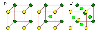
Bravais Lattices
In two dimensions, periodic
unit cells can have one of five basic shapes: general parallelogram, general
rectangle, square, 60-120 degree rhombus, and generic rhombus. The last is often
described as a "centered" lattice, a rectangle with an extra point in the
middle, to bring out the rectangular nature of the pattern.
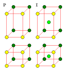
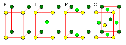
It's not too hard to see the rectangular pattern in a rhombic lattice, but it can be very hard to see the patterns in three dimensional lattices. For this reason, three-dimensional lattices must often be described as unit cells with additional points. There are 14 basic unit cells in three dimensions, called the Bravais Lattices.
|
| The F cell is very important because it is the pattern for cubic closest packing. There is no C cell because such a cell would not have cubic symmetry. |
 |
A C cell would simply be a P cell with a smaller cross-section. An F cell would reduce to a network of I cells. |
            o--------o         o--------o           o
           /:       /|        /:       /|          /|\
          /60   120/ |       / :      / |         / | \
         o--------o  |      o--------o  |        /  o  \
         |  :     |  |      | \:     |  |       o  / \  o
         |  :     |  |      |  :o    |  |       |./   \.|
         |  :     |  |      |  :  \  |  |   =   |/.   .\|
         |  :     |  |      |  :    o|  |       o  . .  o
         |  :     |  |      |  :     |\ |        \  :  /
         |  :.....|..o      |  :.....|..o         \ : /
         | .      | /       | .      | /           \:/
         |.       |/        |.       |/             o
         o--------o (P)     o--------o (R)
The R cell is unique to hexagonal crystals. The two interior points divide the long diagonal of the cell in thirds. This is the only Bravais lattice with more than one interior point. A rhombohedron can be thought of as a cube distorted along one of its diagonals.
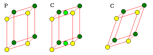 |
| Monoclinic F or I cells could also be represented as C cells. Any other triclinic cell can also be represented as a P cell. |
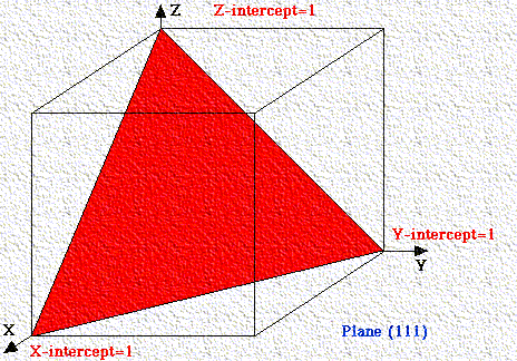
If a plane has negative intercept, the negative number is denoted by a bar above the number. Never alter negative numbers. For example, do not divide -1, -1, -1 by -1 to get 1,1,1. This implies symmetry that the crystal may not have!
Bragg's Law and Diffraction:
Bragg's Law
refers to the simple equation:
nl = 2d sinq (1)
derived by the English physicists Sir W.H. Bragg and his son Sir W.L. Bragg in 1913 to explain why the cleavage faces of crystals appear to reflect X-ray beams at certain angles of incidence (theta, q). The variable d is the distance between atomic layers in a crystal, and the variable lambda l is the wavelength of the incident X-ray beam (see applet); n is an integer
This observation is an example of X-ray wave interference (Roentgenstrahlinterferenzen), commonly known as X-ray diffraction (XRD), and was direct evidence for the periodic atomic structure of crystals postulated for several centuries. The Braggs were awarded the Nobel Prize in physics in 1915 for their work in determining crystal structures beginning with NaCl, ZnS and diamond. Although Bragg's law was used to explain the interference pattern of X-rays scattered by crystals, diffraction has been developed to study the structure of all states of matter with any beam, e.g., ions, electrons, neutrons, and protons, with a wavelength similar to the distance between the atomic or molecular structures of interest.
Bragg's Law can easily be derived by considering the conditions necessary to make the phases of the beams coincide when the incident angle equals and reflecting angle. The rays of the incident beam are always in phase and parallel up to the point at which the top beam strikes the top layer at atom z (Fig. 1). The second beam continues to the next layer where it is scattered by atom B. The second beam must travel the extra distance AB + BC if the two beams are to continue traveling adjacent and parallel. This extra distance must be an integral (n) multiple of the wavelength (l) for the phases of the two beams to be the same:
nl = AB +BC (2).
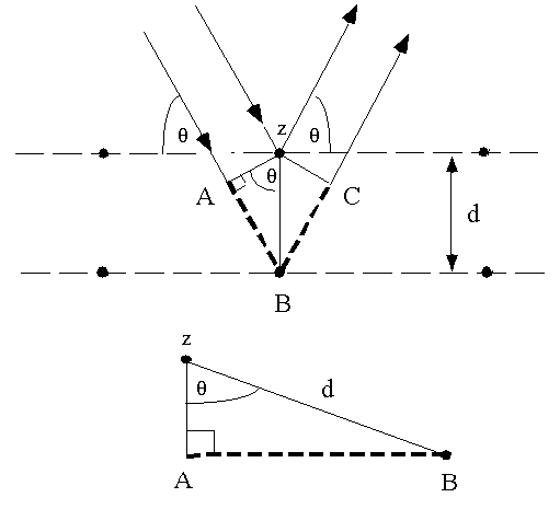
Fig. 1 Deriving Bragg's Law using the reflection geometry and applying
trigonometry. The lower beam must travel the extra distance (AB + BC) to
continue traveling parallel and adjacent to the top beam.
Recognizing d as the hypotenuse of the right triangle Abz, we can use trigonometry to relate d and q to the distance (AB + BC). The distance AB is opposite q so,
AB = d sinq (3).
Because AB = BC eq. (2) becomes,
nl = 2AB (4)
Substituting eq. (3) in eq. (4) we have,
nl = 2 d sinq, (1)
and Bragg's Law has been derived. The location of the surface does not change
the derivation of Bragg's Law.
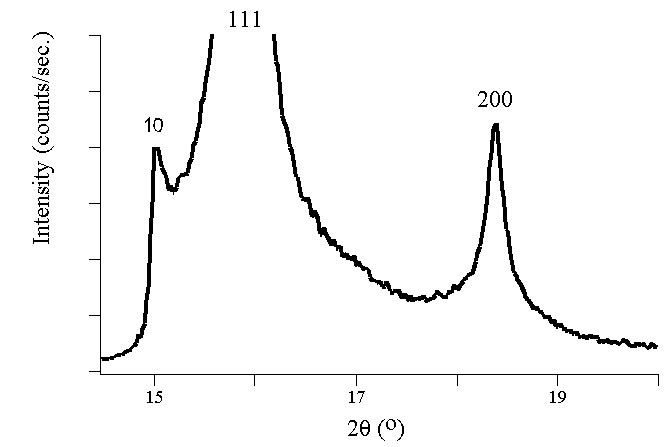
Experimental Diffraction Patterns
The following figures show experimental x-ray diffraction patterns of cubic
SiC using synchrotron radiation. 
Players in the Discovery of X-ray Diffraction
Friedrich and Knipping first observed Roentgenstrahlinterferenzen in 1912 after a hint from their research advisor, Max von Laue, at the University of Munich. Bragg's Law greatly simplified von Laue's description of X-ray interference. The Braggs used crystals in the reflection geometry to analyze the intensity and wavelengths of X-rays (spectra) generated by different materials. Their apparatus for characterizing X-ray spectra was the Bragg spectrometer.
Laue knew that X-rays had wavelengths on the order of 1 Å. After learning that Paul Ewald's optical theories had approximated the distance between atoms in a crystal by the same length, Laue postulated that X-rays would diffract, by analogy to the diffraction of light from small periodic scratches drawn on a solid surface (an optical diffraction grating). In 1918 Ewald constructed a theory, in a form similar to his optical theory, quantitatively explaining the fundamental physical interactions associated with XRD. Elements of Ewald's eloquent theory continue to be useful for many applications in physics.
Scintag XRD Basics (Acrobat PDF Document)
More abuot
XRD
The International Centre for
Diffraction Data® (ICDD®)